
 English
Views: 1 Author: Site Editor Publish Time: 2026-09-23 Origin: Site

Relay protection serves as the primary safety barrier for modern substations. When faults including short‑circuits, overloads and ground faults occur on transmission lines, transformers and busbars, protective relays must quickly detect abnormal conditions and issue trip commands to isolate faulty sections. This prevents widespread power outages and permanent damage to expensive primary equipment.
Nevertheless, long‑term field operation causes parameter drift, contact wear and logic defects in both electromagnetic and numerical protection devices. Regular commissioning and preventive maintenance with professional relay testers are essential to validate pickup thresholds, operating timing and overall protection logic. Hidden failures inside protection relays will stay undetected without proper secondary‑injection testing, posing serious risks to power grid security.
CHONGQING GOLD’s GDJB‑PC 3phase relay protection tester and GDJB‑PC 6phase relay protection tester are field‑oriented secondary‑injection test sets adopting DSP+FPGA hardware architecture. Both models generate high‑fidelity fault voltage‑current waveforms and support testing for legacy electromagnetic relays and mainstream microcomputer‑based protection units. This article introduces core test workflows, common field pitfalls and practical advice for maintenance and commissioning crews.
▎Note: Core design specifications follow DL/T 624‑1997 (superseded industry standard); its test methodologies remain consistent with modern field‑site working practice. Evaluation against the current DL/T 624‑2023 standard is in‑progress.


Test Items
Four high‑frequency test scenarios for substation protection work are detailed below, along with how GDJB‑PC series optimizes on‑site operations.
1. Distance Protection Test
Impedance protection is widely deployed for 110 kV and higher voltage transmission lines. It divides fault detection into Zone 1, Zone 2 and Zone 3 according to measured impedance values. Field tests verify impedance settings, zone boundary performance, forward reverse fault discrimination and trip timing for phase to phase and phase to ground faults.
Field challenge:Technicians need to inject multiple groups of current‑voltage signals at 0.7 ×, 0.95 × and 1.05 × of preset impedance values. They must record trip responses and check time coordination between protection zones. Manual calculation and repeated parameter adjustment consume plenty of time and easily introduce human error.
GDJB‑PC practical solution: The built‑in Impedance Ladder Test module supports fully‑automated batch testing for multi‑zone distance protection. After inputting impedance settings, zero‑sequence compensation coefficient and target fault types —phase A earth fault, AB short circuit, etc, the tester automatically changes impedance multiples, captures trip signals via binary input channels, records operating time and generates complete test reports.
Model guidance: GDJB‑PC 3, equipped with 3‑phase current plus 4‑phase voltage outputs, covers most routine distance‑protection maintenance tasks including single‑phase‑earth and common phase‑to‑phase fault simulation. GDJB‑PC 6 is recommended for complex multi‑terminal line‑protection commissioning scenarios requiring richer multi‑fault signal simulation.
2. Differential Protection Test
Transformer differential protection is the main protection for power transformers. Testing covers proportional restraint characteristics, harmonic restraint thresholds and differential pickup current. Correct testing avoids nuisance tripping caused by magnetizing inrush while guaranteeing reliable action for internal winding failures.
Field challenge: Operators have to simulate restraint current and differential current for high‑voltage and low‑voltage sides. They also need to configure transformer vector groups (Y/Y‑12, Y/Δ‑11) and CT‑ratio‑based balance coefficients. Three‑phase testers face obvious limits for full‑signal simulation of two‑winding or three‑winding main transformers.
GDJB‑PC practical solution:
GDJB‑PC 6: Equipped with genuine six‑phase independent current‑voltage outputs, it directly injects differential and restraint signals for high‑side and low‑side windings. Its dedicated Differential Test module contains pre‑configured transformer connection groups. Balance coefficients can be auto‑calculated by feeding in transformer capacity, rated voltage and CT ratio data. It conducts boundary‑search and fixed‑point tests for proportional restraint and second‑harmonic restraint, and outputs characteristic curves automatically.
GDJB‑PC 3: Fit for simple differential‑relay checks of small‑capacity equipment through combined three‑phase‑current simulation. GDJB‑PC 6 is strongly suggested for main‑transformer commissioning projects.
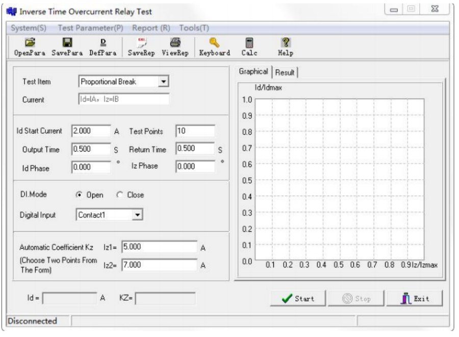
3. Overcurrent Protection Test —Inverse Time Overcurrent Included
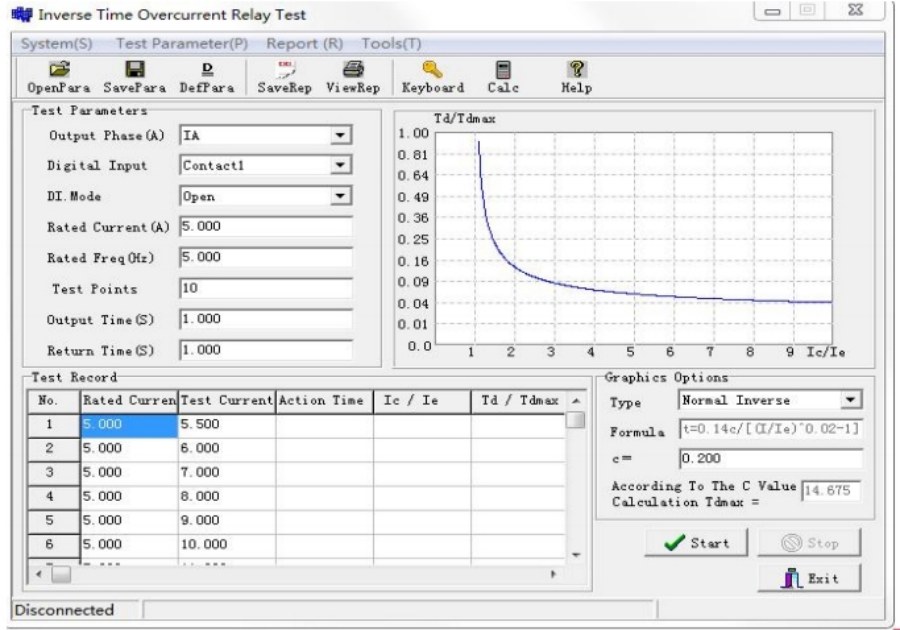
Overcurrent protection includes instantaneous overcurrent, definite‑time and inverse‑time overcurrent functions. It acts as primary feeder protection as well as backup protection for transformers. Key test points are pickup current, dropout value, return coefficient and inverse‑time current‑operating‑time curves.
Field challenge: Inverse‑time characteristic tests demand multi‑point sampling for current‑time relationships. For old‑style electromagnetic relays, contact bounce may trigger misjudgment of action and return values.
GDJB‑PC practical solution: The AC Test and Inverse‑Time Over‑Current Relay modules support manual or automatic ramping of current output. Technicians set amplitude step size and contact jitter‑delay parameters to filter bounce interference from mechanical contacts. The tester automatically computes return coefficients and draws inverse‑time curves for test reports. Both GDJB‑PC 3 and GDJB‑PC 6 fully handle all categories of overcurrent‑related tests.
4. State‑Sequence / Group Test — Reclosing & Whole Set Simulation
State‑sequence and group‑test functions simulate complete state transitions of power systems: pre‑fault normal operation → fault occurrence → breaker tripping → reclosing action → permanent‑fault trip. These tests validate auto‑reclosing logic, post‑acceleration features, standby automatic switching and overall coordination between protection devices and secondary loops.
Field challenge: Manual switching among multiple working states, precise timing control for each condition, and sequential capture of trip and reclosing contact signals place heavy burdens on field teams.
GDJB‑PC practical solution: The State Series and Group Test modules allow operators to configure multiple custom working states for simulation workflows. Users configure fault nature — transient or permanent fault, pre fault load current, fault holding time and post‑trip waiting duration. The tester outputs sequential voltage current waveforms following preset timing, monitors 8 binary input channels for relay actions, and timestamps every event for comprehensive whole set logic evaluation. An optional GPS synchronization module supports synchronous joint testing using two separate testers at different locations.
Field Practical Tips — Avoid Common Test Pitfalls
Even high‑performance testers produce invalid data or risk equipment damage without standardized field operations. Four practical tips are summarized from CHONGQING GOLD’s on‑site service experience.
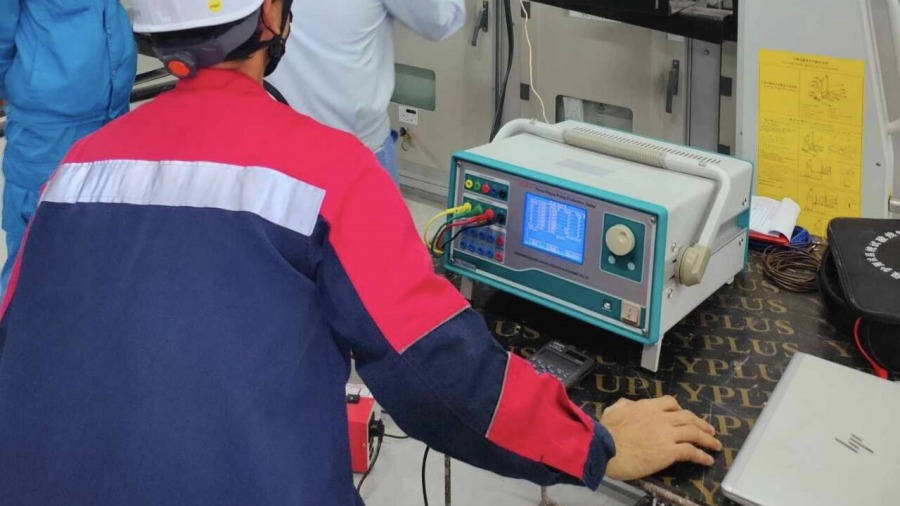
Tip 1: Verify Wiring and Binary‑Input Mode Before Enabling Output
Wrong wiring ranks first among all test‑failure causes.
Make sure voltage and current output terminals are correctly connected to secondary‑circuit terminals of protection devices. Never feed external site power into tester output jacks, or internal power amplifiers will suffer permanent burnout.
Distinguish passive dry contacts and active potential contacts 0‑250 V DC, For active‑potential trip contacts, connect the positive potential terminal to the COM common port of tester binary‑inputs. Reversed polarity leads to failure in capturing action signals.
Check cable terminals for loose connections. Poor contact under high‑current conditions results in overheating and distorted output waveforms.
Tip 2: Strictly Limit Large‑Current Output Duration
GDJB‑PC series supports multi‑phase‑parallel high‑current output, yet heavy‑current signals cannot work continuously.
Follow specification limits: long‑term allowable single‑phase output current is 10 A RMS. Peak large‑current injection must be restricted to 3‑5 seconds.
Set reasonable hold‑time values within software. Avoid keeping high‑current output while adjusting protection‑device parameters. Prolonged heavy‑current output may burn CT secondary terminals or overheat the tester’s power‑amplifier hardware.
Tip 3: Troubleshoot Unstable & Random Action Signals
If relays send irregular, unrepeatable trip signals during stable output:
Raise contact‑jitter‑delay in software: use 10‑20 ms for numerical relays and 30‑80 ms for old electromagnetic relays to filter transient bounce noise.
Check equipment grounding. In substations with heavy electromagnetic interference, fasten the tester’s protective‑ground terminal to the substation grounding grid. Floating ground introduces stray noise into binary‑input sampling channels.
Confirm unrelated protection platens are withdrawn. Extra enabled protection functions may generate spurious trips irrelevant to injected test quantities. Disable redundant protections during single‑function verification.
Tip 4: Cross‑Check All Parameters Against Official Setting Sheets
Many erroneous tests stem from incorrectly copied setting values.
Before launching any automated test, double check pickup values, impedance settings, CT/PT ratios and transformer vector group parameters against official protection setting documents.
After automated batch testing finishes, do not fully trust generated reports. Perform manual spot checks for critical protection functions to eliminate mistakes caused by manual input typos.
Relay protection testing forms a vital segment of substation preventive maintenance. Proper secondary‑injection testing verifies protection‑device performance and secondary‑circuit reliability, eliminating hidden hazards for stable power‑grid operation.
CHONGQING GOLD GDJB‑PC 3 and GDJB‑PC 6 relay‑protection testers integrate abundant professional test modules, high‑fidelity waveform generation and complete hardware safety protections. GDJB‑PC 3 delivers cost‑effective performance for routine maintenance of conventional substations. GDJB‑PC 6 provides six‑channel outputs for complex work such as main‑transformer differential‑protection commissioning and multi‑equipment joint simulation.
Looking for an efficient substation relay protection testing solution?
Please submit your inquiry using the form below. Our team will respond within one business day.
→[Button: Inquire about relay protection testing equipment]
