
 English
Views: 10 Author: Site Editor Publish Time: 2026-08-19 Origin: Site

Technicians with experience in high-voltage field commissioning have often encountered this challenging scenario: the team arrives at the work site, the power outage window is limited, and they are preparing to conduct AC withstand voltage tests on XLPE cables and GIS equipment, but the reactive power output of traditional test transformers cannot meet the test requirements. The generator runs at full load, but the test voltage cannot be raised, forcing project delays.
Resonant testing systems are the solution to these field pain points. Series resonant technology eliminates the need to move bulky traditional test transformers, and by using matching circuit inductance to offset the capacitive load of the equipment under test, it significantly reduces the input power requirement. This practical guide outlines the complete field operation process, explains reactor selection and layout, potential risks in field power supply, common configuration errors, and clarifies the HSE safety guidelines that commissioning and maintenance personnel must adhere to.
Modular frequency converters have become the mainstream solution for power field withstand voltage testing. Large-capacity frequency converter resonant testing systems such as the GDXZ-1300kVA/650kV are representative examples. With their modular and portable advantages, they are widely used for acceptance and preventative testing of cables, GIS busbars, power transformers, and rotating electrical machines.
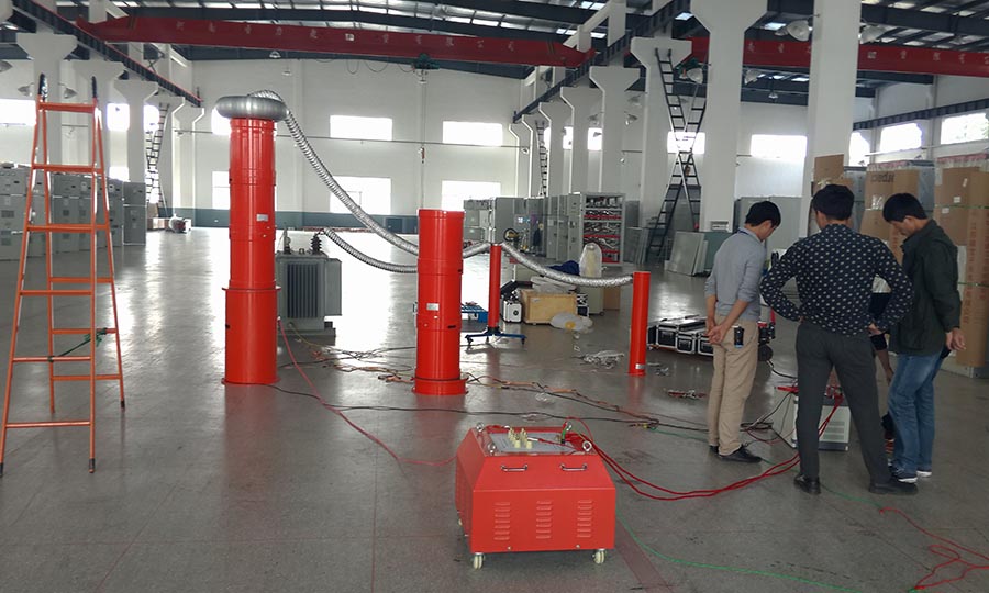
2. Technology of Variable Frequency Series Resonance
2.1 Physical Principle of Power Reduction
The resonant test system is essentially an LCR working circuit. The device under test provides capacitance C; the modular reactor group provides inductance L; conductor loss, corona discharge, and dielectric loss together constitute the circuit resistance R.
When resonance does not occur, the excitation transformer needs to output the full charging current:
I_charge = 2πf · C_test · V_test
Taking a 5 km, 220 kV XLPE cable (0.75 μF), with a test withstand voltage of 316 kV as an example:
I = 316000 × 2π × 50 × 0.75 × 10⁻⁶ ≈ 74.5 A, corresponding to a reactive power of 23.5 MVA. Traditional test transformers of the same specifications are huge in size and weight, and are not suitable for field transportation operations.
After entering the series resonance state, the inductive reactance and capacitive reactance cancel each other out, and the circuit impedance is reduced to only pure resistive losses. Variable frequency power supplies only need to compensate for system active power losses:
P_input = P_test / Q
Mature variable frequency resonant testing systems generally have a Q factor ≥ 30. Reactive power oscillates back and forth between the reactor's magnetic field and the tested equipment's electric field. Once insulation breakdown occurs, the resonant condition disappears instantly, fault current is effectively suppressed, and harmful recovery overvoltages are avoided. Compared to traditional high-voltage testing equipment, the weight and footprint of the entire system are significantly reduced.
2.2 Variable Frequency Power Supply: The System Brain
The VFPS is the core control unit of the variable frequency resonant device. Modern IGBT models automatically sweep the frequency range (30-300 Hz) to search for the resonant point. Operators can switch between three operating modes—fully automatic, automatic tuning-manual boost, and fully manual—depending on the operating conditions.
On-Site Functions:
Customizable frequency sweep range, coupled with a visual interface for the resonant curve, allows for quick identification of the true resonant state.
Closed-loop voltage regulation resists grid fluctuations and is suitable for long-term withstand voltage holding tests.
Multiple protection logics: overvoltage, overcurrent, flashover detuning trip, and hard-wired emergency stop reduce the risk of arc flashover.
On-site test record storage and local printout meet the archiving requirements of third-party witnessed test data.
2.3 International Standard Compliance
Field resonant acceptance testing must comply with global standards recognized by third-party organizations such as DNV, SGS, and Bureau Veritas .
| Standards | Applicable Objects | Key Test Requirements |
| IEC 60840 | XLPE Cables (30-150kV) | AC Withstand Voltage 1.7×U₀, Continuous 1h |
| IEC 62067 | XLPE Cables (150-500kV) | AC Withstand Voltage 1.4×U₀, Continuous 1h |
| IEC 62271‑203 | GIS Equipment | 80% of Factory AC Withstand Voltage |
| IEEE 400.2 | Shielded Power Cables | Approved Resonant Withstand Voltage Test Method |
| IEC 60060‑1 | High Voltage Test Techniques | Specifying Voltage Measurement Accuracy Indicators |
The waveform distortion of industrial-grade field equipment is ≤1%, and the effective value measurement accuracy is Class 1.5 accuracy, meeting the specifications for acceptance testing and preventive testing.
3. How to Configure a Resonance Test Setup: Step-by-Step Workflow
Step 1: Characterizing the Test Object
Before assembling the wiring for the series resonance test, collect the key parameters of the object under test.
| Parameter | Symbol | Source | Typical Value |
| Test Voltage | V_test | Client specification or IEC standard | 1.4-2.0× U₀ for cables; 80% factory test level for GIS |
| DUT capacitance | C_test | Equipment datasheet or field measurement | 0.1-0.5 μF/km for XLPE cables |
| Operating frequency band | f_range | VFPS technical specification | 30-300 Hz |
| Site power source | P_available | Mains power or generator output | 220 V single-phase / 380 V three-phase |
On-site reminder: Capacitors must be measured on-site; do not directly copy the sample parameters. Manufacturing tolerances can introduce a ±10% deviation, directly altering the resonant frequency. Calculate the test current using I = 2πfCU × 10⁻³ (A), allowing for a 25% capacity margin; the Q value will decrease in high-altitude and humid environments, making this margin particularly important.
Step 2: Reactor Series-Parallel Configuration
The series-parallel configuration of reactors directly limits the maximum output voltage and current of the resonant test system. Incorrect configuration is a high-frequency cause of voltage failure in the field.
1. Series Configuration
VFPS → Excitation Transformer → [R1] — [R2] — [Rn] → Test Object
V_total = V₁ + V₂ + … + Vₙ ; L_total = L₁ + L₂ + … + Lₙ
It is selected when the target voltage is higher than the rated voltage of a single reactor; it is mostly used in GIS and high-voltage substation equipment, which have high voltage requirements and small body capacitance.
2. Parallel configuration
┌── [R1] ──┐
VFPS → Excitation Transformer ── [R2] ──┼── Test Object
└── [R3] ──┘
I_total = I₁ + I₂ + I₃ ; L_total = 1/(1/L₁ + 1/L₂ + 1/L₃)
Parallel layout suits high-capacitance DUTs such as lengthy power cables that demand higher test current rather than extreme voltage.
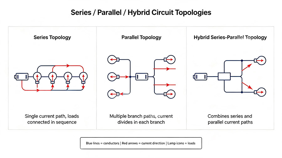
3. Hybrid Series-Parallel Configuration
Taking a typical 132kV cable commissioning condition as an example: a 4.2 km XLPE cable with a capacitance of approximately 1.05 μF. Two reactors in parallel provide sufficient current, but the voltage margin is insufficient to meet the 1.7 × U₀ requirement; three reactors in series meet the voltage standard, but the current per reactor exceeds the 2 A rated current during the withstand voltage maintenance phase.
The final solution is a 2×2 hybrid layout: two parallel branches, each with two reactors in series. This solution balances voltage and current; however, the inductance deviation of each branch must be controlled within ±2%. If the deviation reaches 3% or more, the resulting circulating current will trigger overcurrent protection when only 60% of the target voltage is reached. The consistency of the inductance of the parallel branches must be verified after wiring is completed.
Currently, mainstream modular complete sets of equipment are equipped with multi-tap excitation transformers and capacitor dividers as standard. When using an external compensation capacitor to adjust the total capacitance of the circuit, the compensation capacitor also needs to be connected to a single-point star ground.
Step 3: Calculate and verify the resonant frequency
Resonant frequency calculation formula:
f_resonant = 1 / (2π√(L_total × C_test))
Verify that f_resonant falls within the 30-300 Hz operating range:
f < 30 Hz: Increase the series inductance, or conduct the test on large capacitor samples in segments.
f > 300 Hz: Reduce the total inductance, or connect a compensation capacitor in parallel.
During automatic frequency sweep, the start and end frequency interval should be at least 50 Hz to ensure stable resonance locking. For unknown samples, use a full-band sweep of 30-300 Hz; for known capacitor equipment, narrow the sweep window, shorten the test time, and reduce device losses.
Step 4: 220V and 380V Test Power Supply
Power supply assessment errors are the most costly pitfall in deploying a frequency converter resonant test system. The feasibility of 220V and 380V test power supplies must be assessed before the equipment is put into operation.
When the VFPS is connected to a three-phase 380V input, it outputs full power; when connected to a single-phase 220V, the equipment is derating for protection, outputting only 50% of its rated capacity. This is due to hardware protection logic, not a equipment failure. The root cause is increased single-phase rectified ripple, leading to increased thermal stress on the power devices.
Equipment allocation pre-allocation calculation logic:
Calculate the test reactive power S_test based on the sample parameters.
Calculate the input power requirement: S_input = S_test / Q_expected
Available power: Three-phase 380V uses the rated full value; single-phase 220V uses 50% derating value.
Typical Calculation Example:
Assume a tropical construction site has only 220V single-phase power supply. Theoretically, with Q=50, the test sample requires an input power of 42 kVA. After derating, the power supply appears to have a margin of 50 kVA on paper.
However, at midday when the ambient temperature reaches 38°C, the equivalent resistance of the circuit increases, and the actual Q value drops to 38. The actual required input power surges to 55 kVA, exceeding the derating limit and triggering an overheat shutdown. In such cases, it often takes several hours to coordinate the arrival of a backup generator on-site.
Practical Recommendation: If the calculated S_input exceeds 70% of the usable power after derating, a three-phase generator must be configured. Before the test, set up a multi-stage voltage boost curve, and set the overvoltage protection threshold to 110% of the target test voltage.
Step 5: Complete Circuit Wiring for Series Resonance Test
Standard Topology: Parallel capacitor divider of the device under test → Reactor bank → Excitation transformer → VFPS. All devices are connected to a single-point star grounding point, and then connected to the substation grounding network.
Wiring Sequence:
Level the equipment base and measure the grounding resistance of the star grounding point.
Maintain a distance of ≥3 m between the VFPS and the high-voltage circuit to avoid electromagnetic interference.
Connect all equipment grounding busbars to the star grounding busbar; do not connect the device under test yet.
Connect the VFPS output to the primary side of the excitation transformer.
Connect the transformer secondary to the reactor; keep the high-voltage lead within 5 m and apply anti-corona treatment to reduce additional losses.
Connect the device under test and the capacitive voltage divider in parallel at the high-voltage end of the reactor.
Route the coaxial signal line and power cable of the voltage divider separately, with a spacing of ≥500 mm to prevent signal distortion.
Perform a continuity check point by point. If there is an open circuit in the reactor, transformer windings, or voltage divider circuit, it will be impossible to find the resonant point.
A certified high-voltage testing personnel visually verify all high-voltage wiring.
Prepare for voltage ramp-up test.
Note: The entire series resonance test procedure must be performed by no fewer than two certified high-voltage personnel, and must strictly adhere to the high-voltage safety regulations and on-site safety procedures of the country where the project is located.
4. Safety and HSE Compliance
4.1 Grounding: The Most Common Root Cause of Field Faults
Grounding defects are far more frequent than field personnel imagine, and the symptoms are highly deceptive. A typical fault frequently reported during GIS field commissioning manifests as follows: the frequency sweep process runs normally, but the resonant point cannot be locked; the reactor wiring is correct, and the measured capacitance value matches the sample.
Further investigation often reveals two independent grounding paths in the equipment, forming a grounding loop that interferes with the voltage divider feedback signal, preventing the control system from recognizing the true resonance. Connecting all equipment to a single star grounding busbar eliminates the fault. Poor grounding can also cause voltage readings to drift and become distorted during the withstand voltage holding phase, directly rendering the test invalid during witness testing.
Grounding requirements:
| Project | Requirement |
| Star shaped grounding point grounding resistance | High voltage system ≤ 0.5 Ω |
| Grounding conductor type | Braided copper strip, minimum 35 mm ² |
| Grounding lead length | Up to 5 meters from any component to the star grounding point |
| Topological structure | Only single point star grounding; Strictly prohibit daisy chain grounding |
| Verification | Measure the conductivity of each component before power transmission |
4.2 Thermal Management and Operating Cycle Discipline
The rated load of conventional resonant equipment allows for continuous operation for 60 minutes and short-term withstand of 1.1 times overvoltage; the equipment's operating range is -20°C to +55°C.
When the ambient temperature is >35°C, shorten the continuous withstand voltage duration. Record the device temperature every 15 minutes during long-term withstand voltage operation. If thermal protection trips, disconnect the power supply for sufficient cooling before performing a reset.
4.3 Mechanical Stability and Flashover Protection
Outdoor stacked reactors are at risk of wind-driven tipping; windproof cables must be installed. The equipment tilt angle must be controlled to less than 2°; a base plate must be laid on soft ground; an isolation warning zone must be established with a warning radius ≥ 1.5 times the stacking height. Voltage divider legs must be fully extended.
Verify flashover protection and emergency stop circuits before operation. Energy storage calculation formula:
E_stored = ½ × C_test × V_test²
When energy storage >200 kJ, test the sample in sections or connect an external discharge resistor to reduce the risk of arc flashover.
Frequently Asked Questions
1.Why does a 220V single-phase power supply reduce the resonant test output by 50%?
The ripple after rectification of a single-phase 220V power supply is much higher than that of a three-phase power supply, increasing the thermal load on the internal diodes and DC bus capacitors of the VFPS. The firmware actively limits the output to half of the rated value to prevent component burnout. Many teams overlook this derating; even if the power calculation on paper is sufficient, high temperatures and Q-value degradation will increase the actual power consumption. When only a 220V single-phase power supply can be used in the field, sufficient power margin must be reserved.
2.What are the differences between series and parallel reactor configurations?
Series reactors connected end-to-end achieve voltage multiplication, increasing the maximum test voltage; parallel reactors arranged in parallel achieve current multiplication, increasing the allowable test current of the circuit. When neither series nor parallel connections alone can meet the requirements, a hybrid series-parallel scheme is used to simultaneously consider voltage and current constraints.
3.How to determine whether the test object requires series or parallel reactors?
Calculate the target test voltage V_test and test current I_test based on the rated parameters of the test sample and the measured capacitance, and compare them with the nameplate of a single reactor. If the target voltage exceeds the limit, use series connection; if the test current exceeds the limit, use parallel connection; if both exceed the limit simultaneously, use a mixed series and parallel stack.
4.What is the minimum grounding resistance for high-voltage resonant testing?
The grounding resistance of the star grounding point must be ≤0.5 Ω. Use braided copper tape for single-point star grounding. Daisy-chain grounding will create a dangerous ground loop voltage during flashover.
5.Can a resonant test system be used for DC withstand voltage testing?
No. The resonant system is specifically designed for AC withstand voltage testing. DC withstand voltage testing requires a completely different topology. Mixing the two will damage the VFPS output stage.
