
 English
Views: 6 Author: Site Editor Publish Time: 2026-07-22 Origin: Site

High-current testing is no longer simply a matter of "big enough."
Many people on the front lines of power commissioning hold a long-standing misconception: that as long as a high-current generator's output current value meets the standard, it can successfully complete on-site testing and pass project acceptance. This crude standard might have been barely applicable in the early, simpler scenarios of traditional substations and basic circuit breaker verification. However, today, whether it's the refined operation and maintenance verification in China or the standardized auditing of overseas EPC projects, the acceptance threshold for power testing has been comprehensively upgraded. Simply pursuing a "current value meeting the standard" testing method will create many hidden dangers that are difficult to detect in equipment operation and project acceptance.
 Engineers with years of experience in on-site commissioning know that the key to determining the reliability of power test data and whether it can pass rigorous audits is never a single current parameter, but rather easily overlooked details: the purity of the power frequency current waveform, the output stability under dynamic loads, the accuracy control of different current carrying times, and the drift problem of temperature rise data after long-term operation. These details are precisely the core weaknesses of ordinary high-current equipment.
In field practice, acceptance failures caused by these kinds of problems are commonplace. Conventional current boosters output current containing a large amount of harmonic impurities. Even if the displayed current value meets the standard, when superimposed on the secondary circuit of the current transformer (CT), it directly deviates from the transformation ratio and phase test data, ultimately leading to distortion of relay protection setting verification. Furthermore, after circuit breakers and copper busbar windings undergo prolonged current flow and temperature rise, the circuit impedance continuously and dynamically increases. If the equipment lacks a closed-loop voltage and current stabilization mechanism, the output current will continuously fluctuate and drift, resulting in inconsistent data from multiple retests. This is a frequent cause of audit rejections and rework in domestic and international projects.
The core competitiveness of high-current injection equipment adapted to modern complex power conditions lies in its scenario-based adaptability, rather than parameter stacking. Combining the three major high-frequency testing scenarios in current power engineering—circuit breaker overcurrent protection testing, CT current transformer precision calibration, and electrical equipment temperature rise durability testing—we deeply analyze the pain points of on-site operations and specifically explain how SLQ series high-current generator addresses various practical shortcomings of traditional equipment to meet high-standard engineering acceptance requirements.

Scenario 1: Circuit Breaker Overcurrent Protection Primary Injection Test – Testing the Reliability of the Entire Protection Link
Why can't primary injection be replaced by secondary injection?

Relay protection commissioning mainly involves two methods: primary and secondary injection. These two methods differ fundamentally in their test logic, coverage, and acceptance criteria, and absolutely cannot be substituted for each other in high-standard engineering acceptance.
Secondary injection is a simulated signal test, directly connecting the verification signal to the protection relay terminals. It only verifies whether the relay's logic settings are normal, completely skipping the core links such as the CT primary winding, secondary transmission cables, equipment terminal blocks, and wiring contact resistance. This means that common on-site defects such as loose connections, reversed polarity, abnormal loop impedance, and CT ratio deviations cannot be detected at all. The equipment may appear to pass verification, but protection failure is highly likely after actual commissioning.
Primary high-current injection is currently recognized in the industry as the most rigorous and realistic acceptance method. The entire test simulates the actual short-circuit and overcurrent fault conditions of the power grid. Current enters from the primary side of the circuit breaker, undergoes electromagnetic induction conversion by the CT, and is transmitted completely through the secondary cable before finally reaching the protection device. The entire power link is involved in the test. Any minor hidden danger in the circuit will be directly reflected in the circuit breaker's operating time, tripping logic, and sampled data, comprehensively verifying the operational reliability of the entire protection system.
Real Requirements of Field Operating Conditions for High-Current Equipment
Many people mistakenly believe that circuit breaker overcurrent tripping tests are simple, requiring only a short-term current flow and observation of the tripping action. This is not the case. This test places extremely high engineering requirements on the equipment's instantaneous output capability, waveform quality, short-term stability, and timing accuracy; ordinary civilian current boosters simply cannot meet these standards.
The specifications of equipment in power field environments vary greatly, from hundreds of ampere-level circuit breakers in terminal distribution to tens of thousands of ampere-level main circuit equipment in high-voltage transmission and transformation. The test equipment needs to have full-coverage range adaptability capabilities. The SLQ series breaks through the limitations of conventional equipment ranges, achieving a gradient output from 500A to 25kA. Equipment capacity is selectable from 3kVA to 150kVA, allowing a single unit to cover circuit breaker testing across all scenarios, including residential power distribution, industrial substations, and high-voltage transmission. This eliminates the need for multiple units to operate in rotation, significantly reducing on-site equipment investment costs.
Circuit breaker overcurrent tripping is a short-duration pulse condition operating on the order of seconds, and the core assessment focuses on the equipment's instantaneous peak output capability, which is also a high-frequency failure point for traditional equipment. Conventional current boosters are prone to current drops and value drift under short-term full-load conditions, directly leading to deviations in the calculated operating time. The SLQ series is designed strictly according to international engineering duty cycle standards, achieving stable output at 100% rated current for 30 seconds and continuous operation at 75% rated output for 180 seconds, far exceeding the conventional tripping time of less than 5 seconds for circuit breakers. The stable current output throughout ensures accurate and effective test data.
In overseas EPC projects and authoritative third-party testing, protection operating time is core archived data, requiring extremely high timing accuracy. The SLQ series supports optional 4-6 digit high-precision timers, with precision levels covering 0.5%RDG+5D to 0.1%RDG+1D. This meets the needs of routine maintenance and testing, and is also suitable for demanding scenarios such as scientific research verification and high-precision waveform recording, fully complying with audit-level acceptance standards.
Current waveform quality is an easily overlooked but crucial testing element. Ordinary current boosters on the market have high waveform distortion rates, and chaotic harmonics can interfere with the sampling logic of protection relays, frequently causing equipment malfunctions, failures to operate, and timing deviations. The SLQ series optimizes its internal waveform calibration algorithm, achieving a current output THD of <5%, with a waveform close to a standard power frequency sine wave. This eliminates testing errors caused by harmonic interference at the source, ensuring that test results accurately reflect the actual operating conditions of the equipment.
Scenario 2: CT Current Transformer Calibration – Direct Method Testing Eliminates Fundamental Errors
Why is the industry gradually phasing out the "equal ampere-turn indirect method"?
In the past, to improve commissioning efficiency, the equal ampere-turn multi-turn winding method was commonly used to calibrate CT equipment. While this simple testing method is convenient, it has unavoidable fundamental flaws. The leakage inductance parameters, distributed capacitance, and magnetic field distribution of the manually wound multi-turn simulated winding differ greatly from the actual single-turn primary conductor operating conditions of the equipment. The resulting turns ratio error and phase shift data can only serve as a rough reference and lack legal validity for project archiving and audit acceptance.
With the upgrading of domestic and international power engineering standards, all high-standard State Grid projects and overseas EPC general contracting projects have explicitly phased out the indirect testing method and mandated the use of the direct primary current injection method. This method completely replicates the actual operating conditions of the equipment, and the test data is traceable, verifiable, and auditable, making it the only compliant method for high-precision CT calibration at present. The core design logic of the SLQ series high-current generator is precisely adapted to the stringent requirements of direct CT calibration.
Essential Specifications for High-Precision CT Calibration
The complex operating conditions of power grids in the field inevitably lead to slight waveform distortions, making conventional average sampling equipment prone to systematic data deviations. To meet the demands of high-precision calibration, the SLQ series incorporates a dedicated high-precision measurement CT, supporting dual-mode selection with either a 0.5-class analog pointer meter or a 4.5-digit digital high-precision meter. Equipped with a true RMS sampling algorithm, it can accurately capture the true current value even with slight waveform distortions, completely avoiding sampling errors and ensuring the accuracy of calibration data.
Substations and renewable energy plants often employ a wide variety of CT equipment specifications, with small-ratio metering CTs and large-ratio protection CTs frequently used together. A single-range device cannot meet the calibration needs of the entire station. The SLQ series adopts a full-gradient design from 500A to 25kA, covering the vast majority of power CT equipment specifications on the market. A single device can complete batch calibration of all CTs in the station, eliminating the need to repeatedly purchase multiple devices with different ranges, effectively reducing engineering equipment investment costs.
Under prolonged current-carrying calibration conditions, the current booster regulator and windings continuously heat up, causing dynamic changes in circuit impedance, resulting in output current drift and inconsistent retest data. Addressing this industry pain point, the SLQ series incorporates a dedicated redundancy design, significantly improving the device's thermal operational stability through an impedance voltage margin of >8% and a no-load current margin of >6%. Within the standard duty cycle range, the device's output current exhibits no significant drift, and the consistency of retest data is extremely high, meeting laboratory-level comparative testing standards.
Circuit Operation Test

"The relevant supporting equipment for CT calibration projects can be viewed on the CT/PT integrated analyzer product page."
Scenario 3: Circuit Breaker Temperature Rise Test – Duty Cycle Control and Thermal Management are Key
Essential Difference Between Temperature Rise Test and Protection Test
If circuit breaker protection testing examines the equipment's "short-term burst capability," then temperature rise durability testing tests the equipment's "long-term continuous stability." As a core acceptance item before equipment commissioning, the temperature rise test requires a long period of continuous current flow, allowing the circuit breaker contacts, terminals, and equipment copper busbars to fully heat up to a thermal equilibrium state. This verifies the safety margin for long-term full-load operation and is the most demanding operating condition for testing the thermal management and duty cycle control capabilities of high-current equipment.
Core Capabilities of Engineering-Grade Temperature Rise Tests
Most ordinary current boosters on the market are only suitable for short-term trip tests and are completely incapable of performing temperature rise tests. The core shortcoming lies in the lack of a standardized duty cycle protection mechanism; long-term continuous current flow easily leads to winding overheating, carbon brush wear, and voltage regulator burnout. The SLQ series is specifically optimized for temperature rise testing conditions, accurately differentiating the continuous operating duration at different load rates. It fully complies with State Grid and international power engineering testing standards, offering maximum adaptability:
- 100% rated load: Maximum continuous stable operation for 30 seconds
- 85% rated load: Maximum continuous stable operation for 90 seconds
- 75% rated load: Maximum continuous stable operation for 180 seconds
For long-term thermal balance testing scenarios requiring several hours, the equipment supports segmented flow and intermittent cooling operation modes. It is recommended to stop and cool down for at least 10 minutes after each operation. This operation method not only comprehensively collects the full range of data required for temperature rise testing but also effectively avoids overheating damage, extending equipment lifespan and adapting to various long-term durability testing needs.
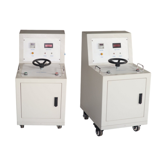
Furthermore, the equipment adopts a scenario-based hierarchical structural design, specifically addressing on-site layout challenges. Small-capacity models of 5kVA and below adopt an integrated design, making them lightweight and quick to deploy. They can be moved and operated by a single person, making them suitable for daily inspections and scattered debugging scenarios. Large-capacity models of 5kVA and above adopt a separate structure for the control unit and current booster, distributing the weight of the equipment and simplifying the wiring layout. They are perfectly suited for batch temperature rise tests of large switchgear and high-voltage equipment, completely solving the practical pain points of traditional large-capacity equipment being bulky, difficult to move, and having messy wiring.
SLQ Series Overall Technical Adaptation and Selection Guide
SLQ series high-current generators are specifically designed for complex power field conditions. Current output ranges from 500A to 25kA, with selectable capacities from 3kVA to 150kVA. They are compatible with a wide operating frequency range of 45~65Hz and support dual AC220V/400V power supply adaptation (matched according to capacity). They can meet the needs of domestic standard power frequency testing as well as overseas engineering scenarios with non-standard frequencies and voltages, offering exceptional versatility.
Equipment structure is designed to perfectly suit the differentiated needs of practical operating scenarios, making the selection logic clear and intuitive. The small-capacity integrated model emphasizes portability and efficiency, suitable for daily maintenance inspections, temporary field commissioning, and short-time protection testing of miniature circuit breakers. The large-capacity split model emphasizes stability and efficiency, specializing in demanding conditions such as large switchgear temperature rise testing, batch calibration of full-station CTs, and precision verification of high-voltage equipment. The equipment also supports personalized customization, allowing for the selection of dedicated current ranges, high-precision timers, and digital/pointer display modes based on project acceptance standards, precisely matching various engineering acceptance requirements.
Here's a crucial on-site operational note: the standard factory configuration does not include a dedicated high-current output cable. The cable's diameter and laying length directly affect the loop impedance and terminal output current. Under high-power, high-current testing conditions, cable voltage drop can easily lead to substandard current and invalid test data. Users are advised to select a suitable dedicated high-current cable based on the on-site operating distance and test current specifications to ensure smooth testing.

Power field testing conditions are complex and varied, and there is never a universal solution that can "one device handle all scenarios." Circuit breaker protection testing focuses on waveform purity and short-time output stability; CT calibration emphasizes overall accuracy and consistency in retesting; and temperature rise testing relies on mature thermal management and standardized duty cycle control. The technical requirements, assessment standards, and operating environments of these three scenarios are vastly different.
The core advantage of the SLQ series lies in its departure from the industry's misconception of simply piling up homogenized parameters. It is entirely based on the real needs of front-line commissioning, project auditing, and acceptance, and its performance is specifically optimized. Whether for routine maintenance and self-inspection, precise calibration by third-party institutions, or high-standard overseas EPC project delivery, it provides stable output adapted to the scenario, and accurate, traceable, and auditable test data. This completely solves the industry pain points of insufficient accuracy, unstable operation, and weak scenario adaptability of traditional high-current equipment, safeguarding the testing and acceptance of various power engineering projects.
