
 English
Views: 5 Author: Site Editor Publish Time: 2026-07-14 Origin: Site

Nowadays, the newly built AI computing power data center distribution rooms and integrated photovoltaic and energy storage stations generally suffer from the problem of dense equipment layout. The cabinet is packed with various protective relays and intelligent acquisition terminals, but periodic performance verification of CT and PT is a mandatory requirement for operation and maintenance. The high-voltage hazards brought by traditional testing methods often damage the surrounding precision digital control boards, which is also a thorny problem frequently encountered in on-site debugging in recent years.
Not exaggerating the risk, Lawrence Berkeley National Laboratory has released statistics on computing infrastructure operation and maintenance losses. Once a large commercial data center experiences a sudden power outage or shutdown, the comprehensive loss generated per minute can reach tens of thousands of dollars. In the scenario of a centralized new energy power station, an unplanned shutdown can directly interrupt the power generation revenue of the entire branch, coupled with equipment maintenance and project delay costs, resulting in significant economic losses.
In this context, CT and PT full project testing cannot be omitted, but the testing operation itself must not become a new source of safety failures.
The industry has been using the power frequency high current one-time injection test for decades, which is precisely the main source of risk on site. The entire set of experimental equipment can weigh up to 50 kilograms, making it time-consuming and labor-intensive for multiple people to collaborate and transport; During the excitation test phase, continuous voltage rise forces the CT magnetic core to saturate, exposing the secondary circuit wiring and intelligent equipment inside the cabinet to high voltage environments for a long time. In the past three years, accidents have occurred at the commissioning sites of new energy stations and data centers in various places, such as over excitation, voltage boosting, flashover, breakdown of protection boards, and burning of sampling channels due to high-voltage reverse power transmission, which has sounded the alarm for the operation and maintenance team.
To avoid such high-frequency safety accidents, experienced frontline debugging personnel have gradually changed their testing approach: abandoning the power frequency high-voltage strong excitation mode and adopting a low-voltage variable frequency detection scheme that changes the testing frequency. This detection method has been validated through a large number of domestic and international projects, and the test data is accurate and reliable. The GDVA-405 CT/PT comprehensive analyzer is a mainstream on-site equipment developed based on this technology route.
Three major practical pain points that have long existed in on-site testing
Pain point 1: High voltage test at power frequency, high risk of damage to weak electrical equipment
The traditional CT excitation characteristic test operation logic is simple and crude, continuously increasing the output voltage until the magnetic core enters saturation state. For the protection level high inflection point voltage CT, the boosting process will instantly generate thousands of volts of instantaneous high voltage.
The wiring in digital distribution rooms and intelligent photovoltaic booster stations is complex, and high and low voltage circuits are arranged in close proximity. Thousands of volts of high voltage can easily cause faults such as reverse power transmission and air gap flashover. Once broken down, the microprocessor and intelligent electronic devices in the cabinet will be directly scrapped, and the entire distribution protection system will fail synchronously. There have been many real cases of such accidents in the industry.
Pain point 2: Traditional experimental equipment is bulky and difficult to access in narrow and cramped environments
The design core of containerized photovoltaic inverter stations and high-density data center rooms is to reduce land occupation and improve space utilization, leaving very narrow channels for experimental operations and equipment transportation.
The weight of old-fashioned high current injection equipment generally exceeds 50kg, and narrow cabinet doors, high-altitude ladders, and equipment interlayers are difficult to pass through. Often, two or three staff members work together to transport the equipment, and it takes half a day to complete the equipment placement, directly compressing the established power outage maintenance window period and significantly slowing down the overall debugging progress.
Pain point 3: The audit standards for overseas EPC projects are strict, and old-fashioned instruments are difficult to meet the standards
The acceptance standards for cross-border general contracting projects will be directly written into the project contract, and multiple sets of IEC and IEEE transformer standards need to be synchronously verified. Auditors will check the test data and original report format item by item.
Traditional universal testing instruments do not have built-in standard automatic verification programs, and all parameter conversion and error determination rely on manual calculation and input. The data format is not uniform, and there is no automatic traceability record for the judgment standards, which easily leads to acceptance rejection and rework retesting. Compared with equipment failures, the time loss caused by audit rework is more difficult to handle.

Core principle of low-voltage frequency conversion detection: precise calculation of high inflection point CT under low-voltage working conditions
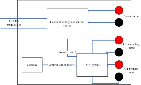
Hardware architecture diagram of GDVA-405 CT/PT comprehensive analyzer
The device is centered around a DSP digital computing unit, connected to a standard AC220V mains power supply, and equipped with a controllable variable frequency constant voltage constant current power source internally. After the upper computer sends test instructions through the communication bus, the DSP module synchronously collects real-time signals from the primary and secondary sides of the CT and dynamically adjusts the voltage and current parameters of the low-voltage variable frequency output; By relying on the built-in magnetic core equivalent calculation model of the device, the excitation curve can be automatically converted without the need to apply high voltage, and the full performance testing of high inflection point transformers can be completed.
1.Why can high inflection point transformer detection be achieved solely through low-voltage output?
The core theory relies on the excitation basic formula V=2 π fLI of the transformer, and the excitation voltage is positively correlated with the test frequency. After lowering the frequency of the test signal, the output voltage required to reach the same magnetic flux saturation state will decrease synchronously.
The GDVA-405 machine only outputs AC low voltage within the safe range of 0.1~180V, with a maximum output effective current of 5A. It is equipped with a 500VA high-power output module, fully covering all working conditions of photovoltaic, energy storage, data center CT, PT excitation tests.
2.Multi frequency data collection, equivalent conversion to 50/60Hz rated operating conditions
The device automatically switches multiple sets of test frequencies to collect raw data of magnetic core excitation, and has a dedicated mathematical equivalent model built in to complete the conversion. The low-frequency collected data is accurately converted into the actual performance curve under the standard power frequency of the power grid. The complete test link is as follows:
Low voltage AC output → Frequency conversion multi-point sweep acquisition → Equivalent model calculation of magnetic core → Extrapolation of power frequency inflection point curve
The entire conversion algorithm has undergone extensive laboratory comparisons, and the final output data has a very small deviation from the traditional high-pressure injection flow measured values, fully meeting the accuracy requirements for power engineering acceptance.
3.Maximum measurable inflection point potential is 45kV, and no high voltage is required throughout the entire process
By relying on the frequency conversion data extrapolation algorithm, the instrument can accurately calculate the maximum CT inflection point voltage of 45kV without applying thousands of volts of high voltage in the secondary circuit, and draw the complete excitation characteristic curve of the entire section. Avoiding the hidden danger of secondary circuit flashover and breakdown from the root, and completely solving the industry's common problem of frequent damage to weak current equipment in high-voltage testing in the past.
4.Balancing safety and high precision, the experimental data meets laboratory standards
While optimizing the safety of on-site operations, the equipment did not sacrifice detection accuracy. CT variable ratio measurement covers the full range of 1-35000, and errors in different intervals are strictly controlled and graded
The transformation ratio is within the range of 1-2000 measurement levels, and the overall error is controlled within 0.05%;
In the range of 2000~5000, the error is less than 0.1%;
The variable ratio of 5000~35000 provides a large range protection CT with an error not exceeding 0.2%.
Overall error of phase angle measurement is ± 2 arcminutes, and the minimum resolution can reach 0.01 arcminutes. The data accuracy in measurement, protection and calibration scenarios can be benchmarked against professional laboratory equipment.
Standardized compliance and full process data management significantly reduce audit workload
Compatible with multiple international standards, suitable for various project acceptance at home and abroad
The acceptance of overseas new energy and data center distribution projects cannot be separated from the complete set of international transformer specifications. GDVA-405 is equipped with an intelligent judgment algorithm that synchronously adapts to IEC 60044-1/2/5/6, the new IEC 61869 series, and the commonly used IEEE C57.13 transformer standard in the North American market.
After the on-site testing is completed, the instrument automatically matches the corresponding standards to complete data judgment, without the need for staff to manually check the thick standard manual. The exported original report can be directly submitted to the audit institution, eliminating the additional process of manual sorting and proofreading.
Fully automatic range switching eliminates measurement errors caused by manual gear selection
The entire testing process automatically switches measurement gears without the need for manual adjustment by operators. The measurement capabilities of each core test item are summarized as follows:
| Test project | Measurement range | Minimum resolution | Measurement accuracy of the whole machine |
|---|---|---|---|
| Transformer winding resistance | Up to 8k Ω, automatic switching between 5 levels of 2 Ω/20 Ω/80 Ω/800 Ω/8k Ω | 0.1mΩ | <0.2% reading+0.02% full scale |
| CT secondary load impedance | Up to 160 Ω, four speed automatic adaptation | 0.001Ω | <0.2% reading+0.02% full scale |
| PT secondary load impedance | Up to 80k Ω, automatic switching in three levels | 0.1Ω | <0.2% reading+0.02% full scale |
| AC voltage measurement | 1V/10V/70V/200V automatic switching | — | <± 0.1%+0.01% full scale |
| AC current measurement | 0.1A/0.4A/2A/10A multi gear adaptive | — | <± 0.1%+0.01% full scale |
PT ratio detection also covers all specifications of transformers from 1 to 35000, with an error of less than 0.2% in the range of 1 to 5000 and a large range error controlled within 0.5% in the range of 5000 to 35000; The overall measurement error of PT phase angle is less than 9 arcminutes, which can fully verify the measurement and protection performance of voltage transformers.
Local high-capacity storage, with permanently traceable test data
The local storage space of the instrument can store more than a thousand complete original test records. The on-site environmental temperature is collected synchronously for each detection, with a temperature measurement range covering -50~100 ℃ and a temperature measurement error of less than 3 ℃. The temperature data is bound and archived with the test curve and error parameters.
During annual equipment inspections, fault tracing, and third-party audits, historical test data can be accessed for horizontal comparison at any time, without the need to browse through piles of paper test records, greatly improving the efficiency of data verification.
The whole machine is lightweight and can be transported by one person
The overall dimensions of the machine are 485mm × 356mm × 183mm, and the weight of the machine is less than 15 kilograms. Compared with traditional 50 kilogram testing equipment, the weight has been reduced by more than two-thirds.
Whether it is the narrow passage between photovoltaic power plant modules or the dense cabinet aisle in data center rooms, which traditional instruments cannot enter, this equipment can be carried and transported in place by a single person. The power supply is compatible with the general mains AC 220V (± 10%, 50/60Hz), without the need for a dedicated regulated power supply. The test can be conducted by plugging it in on site.
The body has been optimized for protection against complex working conditions in outdoor and enclosed computer rooms, with a stable operating temperature range of -10 ℃~50 ℃ and a maximum tolerance of 90% humidity without condensation. Whether it is outdoor high-temperature operations at photovoltaic stations in summer, enclosed and humid environments in computer rooms, or outdoor low-temperature maintenance in northern winter, the equipment can output stably and is fully suitable for both outdoor and computer room scenarios, not just for constant temperature laboratory environments.
Complete technical specifications reference for the entire machine
| Testing Items | Detailed specifications and parameters of the equipment |
|---|---|
| Adaptation testing standards | IEC 60044-1/2/5/6、IEC 61869-2、IEEE C57.13 |
| Whole machine power supply | AC 220V ±10%,50/60Hz ±10% |
| AC output voltage | 0.1~180V(low voltage safe range) |
| Output test current | effective value of 0.001~5A |
| Rated output power | 500VA |
| Equivalent maximum inflection point potential | 45kV(extrapolated by frequency conversion algorithm) |
| CT variable ratio detection range and accuracy | 1~35000; 1~2000 error<0.05%, 2000~5000 error<0.1%, 5000~35000 error<0.2% |
| CT phase measurement index | overall error ± 2 arcminutes, minimum resolution 0.01 arcminutes |
| Winding DC resistance test | with an upper range of 8k Ω and a resolution of 0.1m Ω |
| CT secondary load measurement | maximum 160 Ω, resolution 0.001 Ω |
| PT secondary load measurement | maximum 80k Ω, resolution 0.1 Ω |
| PT ratio detection accuracy | 1~35000; 1~5000 error<0.2%, 5000~35000 error<0.5% |
| PT phase angle error | overall less than 9 arcminutes Human computer interaction screen, 12.1-inch industrial grade touch scree |
| Human computer interaction screen | 12.1-inch industrial grade touch screen |
| Local data storage | supporting over 1000 complete test records |
| Long term working temperature | -10℃ ~ 50℃ |
| Allowable environmental humidity | ≤90%(no condensation)) |
| Overall dimensions of the machine | 485mm × 356mm × 183mm |
| Whole machine weight | less than 15kg |
The most practical requirement for returning to frontline debugging is that CT and PT periodic verification cannot be omitted, but experimental operations should not cause additional secondary problems such as equipment damage, project delay, audit rework, etc. The core solution of the GDVA-405 equipment is very clear: relying on low-voltage frequency conversion technology to avoid high-voltage breakdown risks, ensuring the accuracy of test data through equivalent algorithms, and simplifying the overseas project audit process with built-in standard automatic judgment function.
Whether it is a large computing power data center distribution room or a centralized photovoltaic and energy storage boosting station, this low-voltage frequency conversion detection solution can adapt to various complex working conditions on site.
If bulky old-fashioned power frequency injection equipment is still being used on site, and there is a long-term concern about the damage of intelligent devices in the cabinet caused by excitation high voltage, or if a lot of time is spent manually organizing test reports and replacing low-voltage variable frequency integrated transformer testers for each project acceptance, all of the above on-site pain points can be effectively solved.
If you are advancing the data center and photovoltaic energy storage distribution general contracting project and want to confirm whether GDVA-405 can match the specific testing difficulties on site, you can leave a message or communicate via email, and we will send the complete product specification sheet.
