
 English
Views: 0 Author: Site Editor Publish Time: 2026-10-21 Origin: Site

Shunt reactors are critical reactive‑power compensation assets for high‑voltage transmission networks. They stabilize system voltage, absorb excess capacitive reactive power from long lines, and maintain grid operating quality. However, hidden mechanical and electrical defects such as inter‑turn short‑circuits, winding displacement and core loosening may develop over years of operation. If these faults remain undetected, they can escalate into catastrophic reactor failure and unplanned grid outages.
Traditional field inspection workflows are often constrained by cumbersome disassembly‑dependent test procedures. Non‑disconnecting inductive reactance measurement has emerged as a highly‑efficient supplementary diagnostic solution, allowing maintenance crews to assess reactor health without removing high‑voltage bus connections.
【Note: CHONGQING GOLD GDRG‑H is primarily engineered as an automatic capacitance‑inductance tester for high‑voltage shunt capacitor banks, with additional inductance‑measuring capability for reactors; it is not a dedicated shunt‑reactor analyzer.This article explains the underlying principles, real‑world pain‑points, diagnostic capability and practical value of this testing methodology.】

1. What Does Inductive Reactance Measurement Mean for Power Reactors?
The Core Definition
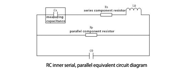
Inductive reactance describes an inductor’s opposition to alternating‑current flow, defined by the well‑known formula:
XL=2πfL
Where f = operating frequency, L = winding inductance.
For shunt reactors, inductive reactance directly determines rated reactive‑power output. Any physical change inside windings or magnetic cores will alter inductance value, which is reflected as measurable deviation of inductive reactance. By comparing measured XL against factory baseline data, engineers can judge internal structural integrity of the reactor unit.
Why Resistance Isn't Enough
Many field teams rely solely on DC resistance (DCR) testing for reactor condition assessment. DC resistance measurement works well for identifying complete conductor breaks or severe connection deterioration. However, DC resistance shows very limited sensitivity to early‑stage inter‑turn short‑circuits or minor winding mechanical displacement.
A small number of shorted turns will barely shift total DC resistance value, while already significantly modifying winding inductance and inductive reactance. Mechanical shifting of core assemblies also produces almost no change in DC resistance, yet distorts magnetic‑circuit characteristics and alters XL. Consequently, relying only on DCR measurements creates blind spots for incipient reactor faults. Inductive reactance testing fills this gap, since it is highly sensitive to subtle internal mechanical‑magnetic variations.
2. The Traditional Pain Point: Why Disconnecting Cables is Ruining Your Efficiency
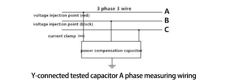
Conventional reactor inductance testing previously required complete disconnection of high‑voltage bushings, bus‑bar jumpers and associated cable terminations before measurement could start.
This workflow brings multiple severe field‑operation drawbacks:
Massive time consumption: Disconnecting and re‑torquing high‑voltage connections can consume several working hours per reactor phase, extending scheduled outage windows.
Risk of mechanical damage: Repeated disassembly of bus‑bar joints and high‑voltage bushings introduces risks: flange mis‑alignment, oil leakage for oil‑immersed reactors, damaged contact surfaces, and improper re‑assembly. Post‑test connection errors may create brand‑new hidden defects.
Higher labor cost: Multiple qualified technicians are required for high‑voltage hardware handling. Longer outage durations also generate indirect economic losses for grid operators.
For asset‑conscious utilities, these drawbacks drive strong demand for reliable non‑disconnecting test techniques.
3. The Breakthrough: How Modern Testers Measure Inductive Reactance Without Disconnecting
CHONGQING GOLD GDRG‑H Automatic Capacitance Inductance Tester is primarily designed for on‑site measurement of high‑voltage shunt capacitor banks. It also delivers secondary inductance‑reactance measuring capability which may be applied for shunt‑reactor evaluation, eliminating the requirement to dismantle bus‑bar and high‑voltage connecting hardware under qualified field conditions.
▍GDRG‑H Key Inductance‑Measuring Specifications (secondary function, not dedicated‑reactor‑tester full‑acceptance specs)
| Parameter | Specification |
|---|---|
| Inductance measuring range | 100 μH ~ 50 H |
| Inductance measurement accuracy | ±2 % of reading |
| Inductance‑mode open‑circuit test output | AC 3 V ±20 %, 50 Hz |
| Maximum test output current | 20 A |
| Measurement architecture | Four‑terminal measurement technique |
The Calculation Principle
The instrument adopts the improved voltage‑current (V‑I) synchronous sampling method and implements four‑terminal measurement techniques to eliminate test‑lead resistance interference. Built‑in high‑precision AC excitation source injects test signals onto reactor terminals. Dual‑channel high‑speed 16‑bit AD converters synchronously sample instantaneous voltage and current waveforms at test terminals.
By processing amplitude and phase‑angle difference between sampled voltage and current, the tester calculates full complex impedance, separates resistive component and reactive component, and derives true inductance L together with inductive reactance XL.
▎Important field‑application limitation: Non‑disconnecting measurement cannot fully isolate the influence from external parallel such as adjacent‑phase windings, bus‑to‑ground capacitance or parallel‑connected equipment. Acceptable engineering‑grade accuracy can only be achieved under typical substation conditions where the impedance of external parallel branches is substantially higher than the impedance of the measured reactor branches unit. Measurement error will increase if parallel‑loop impedance is comparable to the DUT impedance.
Overcoming Field Noise
Substation sites contain heavy 50/60Hz electromagnetic interference from adjacent high‑voltage apparatus. GDRG‑H integrates multi‑stage digital filtering algorithms together with automatic range‑switching and gain‑adjustment modules. It suppresses stray industrial‑frequency noise, stabilizes waveform sampling quality and guarantees repeatable measurement data under harsh on‑site EMI conditions.
4. Typical Faults Diagnosed via Inductive Reactance Deviations
By comparing measured inductive‑reactance / inductance readings against factory‑supplied baseline values or phase‑to‑phase reference data, maintenance engineers can identify representative reactor failure modes:
Noticeable drop of inductive reactance: Strong indicator for inter‑turn short‑circuit. Shorted winding turns reduce effective coil inductance, which lowers measured XL. Even early‑stage partial inter‑turn insulation damage can produce detectable deviation before obvious overheating appears.
Unstable, drifting inductive‑reactance readings: Points toward core loosening or winding mechanical displacement. Loose core clamping structures, shifted core air‑gaps or winding movement modify magnetic‑circuit reluctance; inductance and reactance readings fluctuate across repeated measurements.
▎Note: Inductive reactance deviation serves as key supplementary diagnostic evidence. Comprehensive assessment should also combine loss‑factor, environment temperature, historical trend data, and, where required, testing results from dedicated reactor analyzers for final fault conclusion.
Non-disconnect inductive reactance measurement has become a valuable auxiliary testing method for predictive maintenance in modern substations. It eliminates the cumbersome work of disassembling and reassembling high-voltage busbars, detects early-stage inter-turn and mechanical defects in reactors that are difficult to find with DC resistance testing, shortens power outage time, and reduces asset management risks. However, for scenarios involving comprehensive factory acceptance testing of reactors and in-depth fault diagnosis, dedicated reactor testing equipment should still be prioritized.
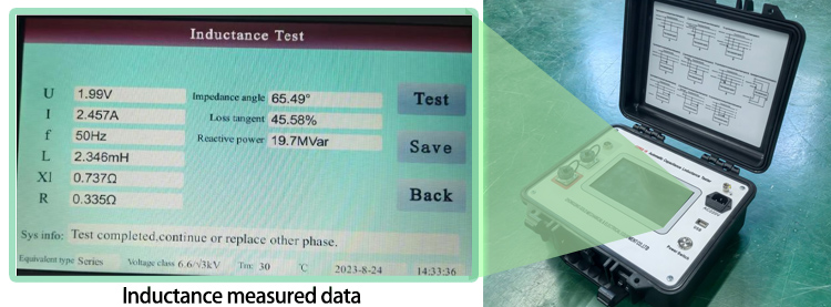
CHONGQING GOLD GDRG-H fully automatic capacitance and inductance tester is primarily designed for on-site testing of high-voltage parallel capacitor banks, and also includes reactor inductance and reactance measurement functions. It features local storage, USB data upload, and standardized report export to a PC, meeting the complete testing workflow of the maintenance team.
Need complete performance parameters for reactors and capacitor banks after testing? Please submit an inquiry.
[Click here to request a quote]
